Eulerian Embroidery

New craft for Spring 2023

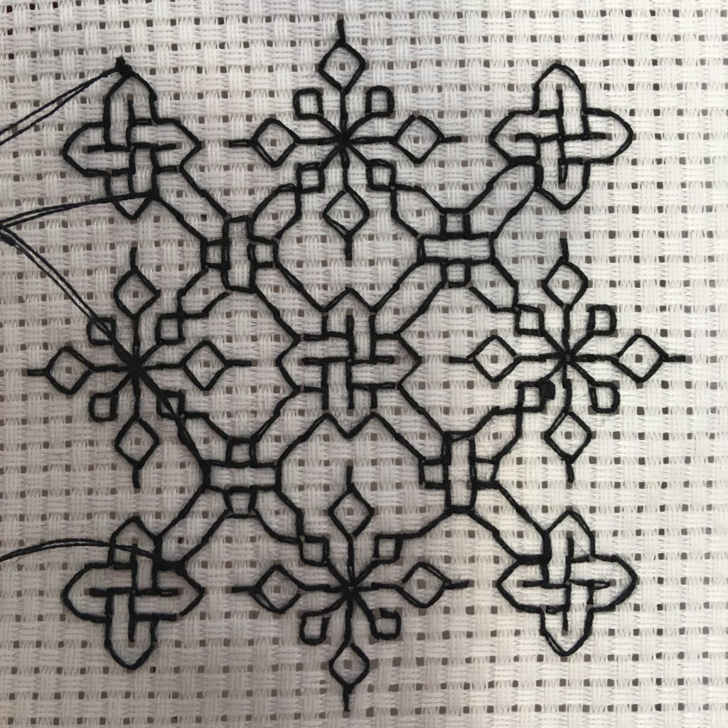
Our new craft for Spring 2023 is a type of embroidery known as “blackwork”, which can be analyzed using the tools of graph theory in an interesting way!

The name “blackwork” comes from the fact that typically this type of embroidery is worked in black thread. It was very popular in 16th century England (where it was also called “Spanishwork” due to a mistaken belief that Catherine of Aragon had introduced it to the country). When worked in red thread it was called “scarlet work” – you get the idea!

Blackwork embroidery is what we call reversible embroidery, meaning that it looks nice on both sides of the fabric (although naturally the pattern is mirrored):

Example based on a pattern from https://www.blackworkarchives.com and sewn by Jane Butterfield.

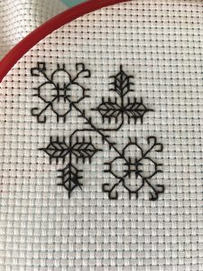
Compare this with something like cross-stitch, which can be really messy on one side of the fabric.

In order to produce a nice-looking, tidy, and efficient piece of embroidery you want to make sure no stitches are duplicated. In other words, for each segment of your pattern you want to have exactly one stitch on each side of your fabric – no doubling up! The mathematical question then arises: what patterns can be embroidered in this way with a single (possibly very long) piece of thread? It turns out that this question can be answered with graph theory, and if you are interested to learn more here is a paper about it: The Graph Theory of Blackwork Embroidery, by Joshua Holden.

Warning: graph theory!

Briefly, we will represent the pattern with a multigraph by adding vertices where the holes in the fabric would be and by adding two edges (one for each side of the fabric) where the pattern says stitches should be. The multigraph below represents a very boring pattern – just a straight line that is seven stitches long!

A path with each edge doubled.

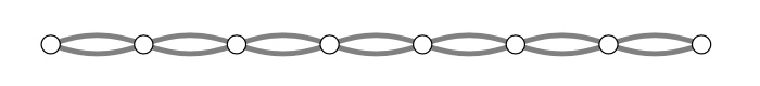
When embroidering in a running stitch, we alternate sides of the fabric. That means we want to find an Eulerian circuit (one that traverses each edge exactly once) with the additional property that if the circuit’s edges alternate red/blue then the graph as a whole will have exactly one red and exactly one blue edge for each original stitch in the pattern. The red stitches then produce the pattern on one side of the fabric, and the blue stitches produce it on the other. The directed blue and red edges below illustrate what happens if you do a running stitch along our boring pattern from the leftmost side to the rightmost side.

The same path, with red and blue directed edges alternating from the leftmost vertex to the rightmost vertex, which uses exactly half of the edges.

If we stopped there, we would have a dashed line (blue edges) on one side of the fabric, and a complementary dashed line (red edges) on the other. To complete the embroidery, in this case, you can simply continue your running stitch back to the leftmost side.

Red and blue directed edges alternate from the rightmost vertex to the leftmost vertex.

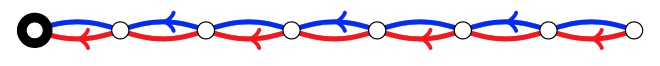
I’ve shown you that you can embroider this particular pattern in this way (Holden calls this a Holbeinian circuit; I’ll say that the pattern is “blackworkable”). It’s not too hard to convince yourself that any length of path is blackworkable. After some trial-and-error you can probably work out how to blackwork embroider any cycle in this way too (the parity of the cycle matters a bit here; odd cycle have more options than even cycles do).

Holden proved that you can in fact embroider any pattern this way as long as it is connected! At one of our Maths & Crafts gatherings in February, we worked through the proof of why this is true.

Resources

Holden’s original paper (preprint) https://www.rose-hulman.edu/~holden/Preprints/blackwork.pdf

Making Mathematics with Needlework: Ten Papers and Ten Projects, edited by sarah-marie belcastro and Carolyn Yackel, has this example and more.

https://www.blackworkarchives.com is a good source of historically inspired blackwork patterns. Be warned that some of them are not connected and will require more than one piece of thread! For practical reasons, you would usually want to use more than one piece of thread anyway, becausevery long threads tend to tangle.

Larger example embroidery.
Larger embroidery sample, based on a pattern from https://www.blackworkarchives.com and sewn by Jane Butterfield.

Sonobe modules

Some of the Maths & Crafts students volunteered in February to help Trefor Bazett run an origami event as part of a day of math and engineering fun on campus (organized in partnership with Let’s Talk Science). Our event centred on Sonobe modules.

What is a Sonobe module? Many origami geometry models are modular, or based on units (see PHiZZ and Wireframe cube). The Sonobe module is a one-paper unit that is named for Mitsunobu Sonobe. It may have been created by Toshiba Takahama (they were coauthors and members of the same origami group), or it may have been invented by someone else and named for the first person to mention it in a publication (in 1968).
Image of a single Sonobe unit.
Sonobe unit.
Use: Three Sonobe modules lock together to form a tetrahedron corner (much like the PHiZZ module).
Three Sonobe units locked together.

One you have folded some Sonobe units, a good starting model is to assemble them into a cube:

Sonobe cube.

You can build other three-dimensional shapes with them too: a “triakis octahedron” or a “triakis icosahedron”. There are some examples of triakis octahedra in the Elliot building origami display, and there is an image of a triakis icosahedron at the end of this post.

The word “triakis” means that each face of the original shape has been replaced by a tetrahedron, which is the Platonic solid formed by four equilateral triangles. Because each face of an octahedron is an equilateral triangle, as is each face of an icosahedron, those shapes are suitable for the “triakis” treatment.

Questions to ponder (some hints below):

  1. How many Sonobe units do you need to build a cube?
  2. If you wanted to “properly colour” your cube, how many colours would you need?  Here we just mean that two papers of the same colour shouldn’t be attached to each other.
  3. Why is the cube special? The other models are “triakis” things; why isn’t the cube?
  4. How many pieces of paper would a triakis icosahedron need? 
  5. How many colours to properly colour the triakis octahedron? triakis icosahedron? (Three are certainly needed, because the units are assembled in trios.)

Resources from Maths Crafts New Zealand

Hints and answers to my questions:

  1. A cub needs six Sonobe modules. There are at least two ways to count it! First way: each Sonobe module is going to end up with its square inner bit being the face of a cube. How many faces has a cube got? Second way: each triple of Sonobe modules is going to form the corner of a cube; how many corners is each module involved in, and how many corners has a cube got?
  2. You’ll need at least three colours for any of these models, because Sonobe units lock together in trios. For the cube, three colours suffice.
  3. The “cube” is actually a “triakis tetrahedron”, so it’s not as special as it seems! This might take some drawing to work out; you might find it helpful to imagine what is left over if you slice each vertex off of a cube.
  4. An icosahedron has 20 faces, each of which is replaced by a trio of Sonobe units, and each unit participates in two faces, so you need 30 pieces of paper.
  5. For the triakis octahedron and the triakis icosahedron, three colours suffice (the triakis icosahedron pictured below is properly three-coloured). It is harder to properly three-colour the triakis icosahedron, though!
Sonobe triakis icosahedron.

Menger sponge

The Menger Sponge is a three-dimensional fractal curve; if you have seen the Cantor Set (in one dimension) or the Sierpinski Carpet (in two dimensions), the Menger Sponge will look familiar to you. If you haven’t see those other things then this is a good opportunity to spend some quality time on Wikipedia.

In his book Project Origami, Thomas Hull gives instructions for folding models of portions of the Menger Sponge out of business cards. He also includes this dire warning:

Instructors in any class using this activity should be forewarned that it is normal for students to become addicted to making business card cube structures.

For our final mathematical paper folding project of December, we assembled a Level 1 Menger Sponge model:

Photograph of our Menger Sponge business card model.
Our level 1 Menger Sponge, built out of 120 business cards.

This model used up my entire supply of old University of Minnesota business cards; to make the Level 1 sponge we will need another 2,280 business cards. If you have any defective business cards (former institution, old job title) you would like to donate to our cause, please let me know!