
This week in the Heritage and Historical Archaeology Field Course, we spent the day back on campus learning about 3D modeling and the process of photogrammetry. Creating 3D models is a popular approach to documenting artifacts in the field, as it is a quick and easy alternative to the more time-consuming process of hand drawing and measuring what you’re looking at. Photogrammetry is the process of making 3D models from a series of 2D images that can be captured relatively quickly in the field with one simple tool: a camera. Once the images are captured, they’re taken back to the lab and downloaded into sophisticated software that renders the series of pictures into a 3D model that can be rotated, manipulated, and of course, analyzed. Photogrammetry follows the same underlying principle of human sight that allows us to have depth perception: overlapping fields of view, i.e. parallax. For the 2D photos to be ‘renderable’ into a 3D model, there has to be around two-thirds of overlap between each of the corresponding images.
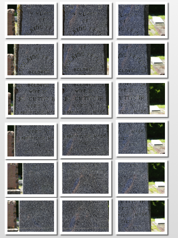
Series of monument (E12) photos with overlapping fields of view taken at the cemetery on May 24, 2018 by Holly Marsh.
During our time on campus, we had the opportunity to turn the series of 2D images we had captured at the cemetery last week into a 3D model. Maddy and I chose to photograph Adelaide Rosetta Gutmann’s monument (plot E12), as the inscription was quite difficult to read in areas and we wanted to see for ourselves how 3D modeling could reveal otherwise obscured inscriptions. We used the software PhotoScanPro to render our model, which took nearly the whole afternoon! The first step was to align the photos – which, brilliantly, the software does for us. It can detect which photos have overlapping fields of view and order them accordingly. The next steps were fairly simple to follow, but each took some time.

Unmodified 3D model of Gutmann’s monument, demonstrating the obscured nature of areas of the inscription. Created in PhotoScanPro.
Once our model was finished rendering, we downloaded the software MeshLab so that we could import our model and analyze it further. One particularly helpful tool on MeshLab to read inscriptions is dynamically relighting the model with the photo texture removed – in other words, altering the angle of the program’s simulated light source to illuminate the inscription by creating shadowed contrasts.
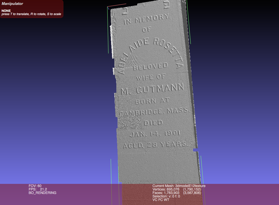
Removed texture and dynamically relit 3D model, showing the improved readability of the inscription. Created using MeshLab.
The process of learning how to build a 3D model – all the way from taking photos at the cemetery to the final product – was exciting. The long rendering time was worth the wait; once imported to MeshLab with the texture removed and the simulated light source adjusted, the model monument’s inscription became incredibly clear and easy to read. Despite some feelings of frustration and impatience during the lengthy rendering process, the experience yielded very satisfying results! I immediately wondered what it would be like to create a 3D model of an entire monument, rather than just the face of it. I’d like to learn/try out that lengthier and probably more complicated process soon!
Dynamic Relighting of 3D model to illuminate the inscription. Video created using QuickTime Player. Model and simulated lighting on MeshLab software.